


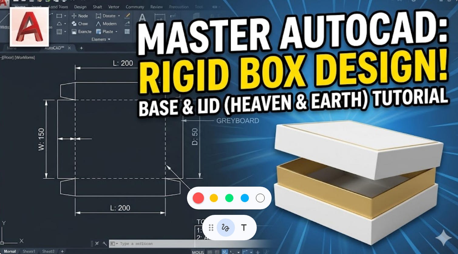
Mastering Base and Lid Rigid Box Design in AutoCAD: A Step-by-Step Guide
Mastering Base and Lid Rigid Box Design in AutoCAD: A Step-by-Step Guide
Published by the Packaging Engineering Team | Essential Guide for Structural Designers
When it comes to premium packaging for electronics, cosmetics, or luxury gifts, the Base and Lid Rigid Box (often referred to in the industry as the “Heaven and Earth” box) is the gold standard. Its sturdy construction and elegant unboxing experience make it a top choice for high-end brands.
However, designing the structural die-line for these boxes in AutoCAD requires more than just drawing rectangles. You must account for material thickness, folding tolerances, and wrapping techniques to ensure a flawless final product that runs smoothly on automated machinery.
In the video tutorial above, we break down the structural design process for a standard 200 x 150 x 50 mm base and lid box. Below is a comprehensive written guide to help you master the core concepts.
1. Establishing the Greyboard Core & Face Paper Die-lines
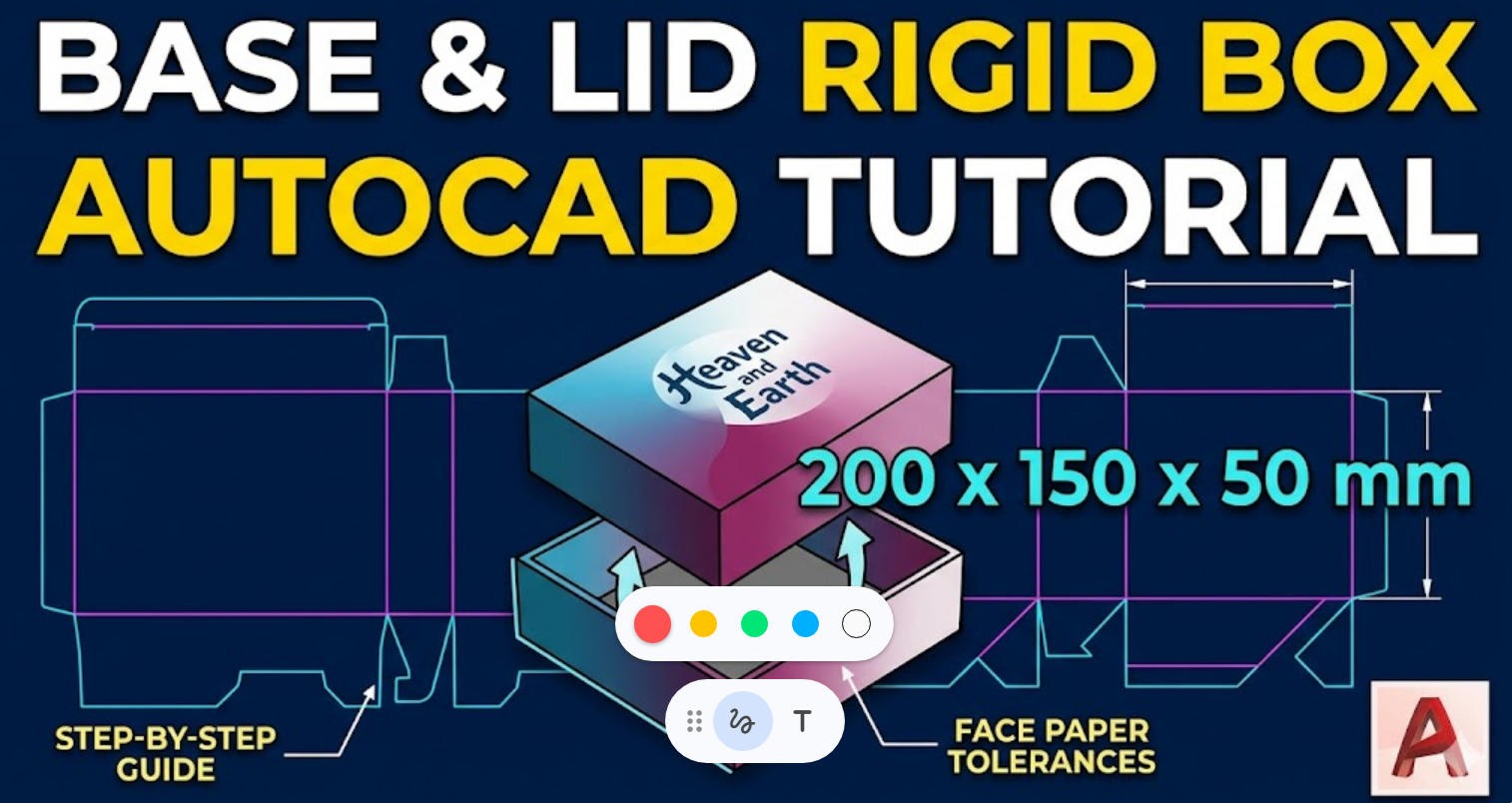
The foundation of any rigid box is the greyboard (or chipboard). For this example, we assume a standard 2mm greyboard thickness. After drafting the precise inner dimensions of your lid, the most critical part is creating the die-line for the face paper that wraps around it.
If your face paper dimensions are exactly the same as the greyboard, the paper won’t wrap properly around the edges. You must build in manufacturing tolerances. For instance, because V-grooves (cuts made into the greyboard for crisp 90-degree folds) aren’t perfectly seamless, you should add a 0.5mm margin around the main face panel to accommodate the fold.
2. Standard Packaging Design Tolerances
To prevent the raw greyboard from being exposed at the corners, you must create slitted overlaps. Proper tolerances also ensure that the final die-lines are perfectly compatible with modern rigid box making machines. Here is a quick reference table for a standard 2mm board:
| Design Component | Standard Specification | Recommended Offset/Tolerance | Engineering Purpose |
|---|---|---|---|
| Face Paper (V-Groove) | 157g Art Paper | +0.5 mm | Accommodates the material thickness during a 90-degree fold. |
| Corner Bleeds | Slitted Overlap | +2.0 mm to +4.0 mm | Prevents exposed greyboard and ensures a seamless corner wrap. |
| Wrap-in Flap | Inner Depth | 15.0 mm to 20.0 mm | Secures the paper to the inside of the box structure. |
| Base Dimensions | Relative to Lid | -4.0 mm (plus 1.5mm – 2.5mm clearance) | Creates a smooth friction fit and allows air release during unboxing. |
3. Calculating the Base Dimensions (The Friction Fit)
The base of the box must nest perfectly inside the lid. To generate the base die-line, you cannot simply use the lid dimensions. Since the lid sits on the outside, you must subtract the thickness of the greyboard on both sides. For a 2mm board, reduce the overall length and width by at least 4mm.
However, if you make the base exactly 4mm smaller, the fit will be too tight. You must add a clearance gap. For larger, deeper boxes, a tight fit creates a vacuum. Increasing your clearance tolerance allows air to escape easily, creating that premium, slow-gliding unboxing experience consumers love.
4. Scaling from Design to Automated Production
Designing the perfect AutoCAD die-line is only the first step. To achieve high-volume, flawless manufacturing, the physical production relies heavily on the precision of the equipment used.
Transform Your Designs into Reality with Kylin Machine Company
Are you looking to scale your packaging production? Perfect die-lines require perfect execution. At Kylin Machine Company, we provide industry-leading printing and packaging machinery designed to handle exact structural tolerances with unmatched speed and accuracy.
From automated V-grooving to intelligent visual positioning for face paper wrapping, our equipment ensures your “Heaven and Earth” boxes are manufactured flawlessly. Contact our engineering team today to find the right machinery for your production line.





Leave a Reply